Basic structure
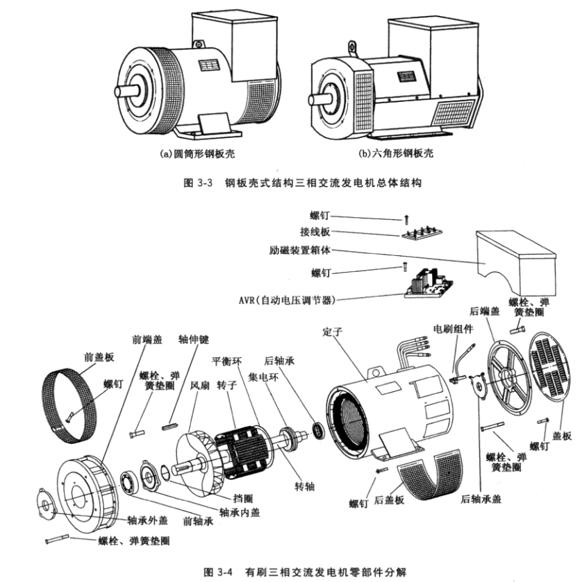
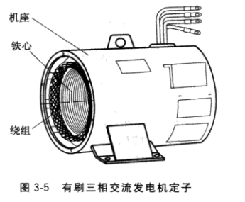
The overall structure of foreign alternators is mostly steel-shell type. The overall structure of small and medium-sized three-phase alternators driven by diesel engines or gasoline engines developed by China is also more and more steel-shell type, as shown in Figure 3-3. Shown. Brushed three-phase alternator is mainly composed of stator, rotor, end cover, bearing, outlet box, etc. The main components are shown in Figure 3-4.
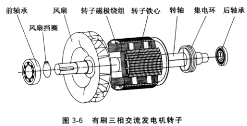
(1) Stator. The stator is made of the base, the stator core, the stator winding sets, shown in Figure 3-5. The base is an integral bracket of the generator for fixing the stator core with windings and supporting the rotor together with the front end cover, the rear end cover and the bearing. The new generator base is made of steel plate, and the inner wall of the base has a plurality of axial ribs evenly distributed along the circumference to support and fix the stator core. Both ends of the base are machined with a stop and a screw hole for engaging with the end cover. The lower part of the base has legs supporting the stator and the whole machine. Stand top or side of ships equipped with outlet box, outlet box with wiring board, then here the AC output lead, the field of stator winding leads and the sub winding wire. Some generator outlet boxes are equipped with an excitation regulator.
The stator core is a component of the magnetic circuit of the alternator, and a core punch made of a certain number of 0.5 mm thick silicon steel sheets is stacked. A certain number of uniformly distributed grooves are circumferentially located near the inner cavity of the core to embed the stator windings. In order to reduce the eddy current loss of the core , the punching sheets are coated with an insulating varnish. The stator core is fixed on the inner circumference of the machine base in one of two ways of external pressing and inner pressing. The external press is the iron core punching sheet which is pressed into a certain length, and is assembled into a whole core by the pressing ring and the buckle under a certain pressure, and then pressed into the base by the stator winding embedding, dipping paint and drying treatment. The inner pressing device is a core punching piece directly laminated on the inner cavity of the machine base and fixed. For the larger capacity alternator stator core, in order to increase the heat dissipation area, the stator core is often divided into several sections along the axial length, and ventilation grooves are provided between each section.
The stator winding is the part of the alternator that induces voltage and outputs electrical energy, and is the core of the generator. The stator windings are embedded in the stator core tip according to the specified method, and are connected into three-phase windings according to a prescribed method. The stator winding of the small alternator is wound by a round-strength polyester enamelled round copper wire. The wire size, the number of winding turns, the number of windings, and the number of parallel paths are specified by the design. The winding forms are double-layered, single-layer chain, single-layer and the like. Three-phase alternators are typically double-stacked windings. The stator windings are embedded in the core slots in the manner specified by the design. Before the rules are placed, slot insulation must be placed in each slot. The three-phase windings must also have phase-to-phase insulation and interlayer insulation. When the alternator is running, the stator winding is subjected to alternating electromagnetic force and electric power parallel to the wire in the core slot, which may cause the winding to vibrate and displace. Therefore, the winding should be fastened and must not be loosened. Generally, it is processed by a glass cloth board. The wedge wedges the windings in the slots, and the ends of the stator windings are fastened with fiberglass tape at both ends.
(2) Rotor. The rotor is generally composed of a rotating shaft, a pole core, a pole winding, a collector ring, a bearing, and a fan, as shown in Figure 3-6.
1 shaft. The shaft is usually machined from No. 35 or No. 45 round steel, and all the components of the rotor are press-fitted on the shaft according to the design specifications. Extension of the alternator shaft on which the coupling, via a coupling alternator with diesel or gasoline docking, the shaft is the mechanical energy into electrical energy critical parts. The rotary shaft of the alternator small - as shrink-yoke, which was after finish together, then each of the other components mounted on the rotary shaft press.
2 pole iron core. The pole core is generally formed by stacking magnetic pole pieces made of a 1 mm thick low carbon steel sheet. By the introduction of foreign technology to produce the unitary pole generator punching, the punching silicon steel made from 0.5mm thick. The pole core is the main component of the rotor magnetic circuit of the generator .
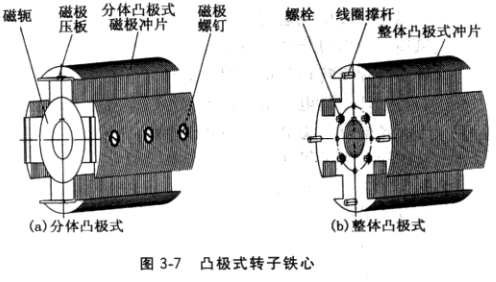
Small and medium-sized alternators, whether single- phase or three-phase, can be divided into salient and hidden poles. The salient pole type refers to the pole of each pole of the pole core being convex , and the pole winding is set on the pole body or directly wound on the insulator. The salient pole pole core has a split salient pole and a salient pole salient pole , which is formed by stacking salient pole pole core sheets as shown in Fig. 3-7, and Fig. 3-7a is a split convex. The pole pole core, each pole core is set on the pole winding, and is fixed on the yoke by a magnetic pole screw; FIG. 3-7b is an integral salient pole pole core, each pole is integrated with the yoke part , and the pole winding is directly wound Made on the pole that has been wrapped with insulation. The generators imported from abroad adopt the overall salient pole structure. The magnetic pole windings have good heat dissipation conditions, high mechanical strength, no second air gap in the rotor, and reduced excitation ampere, and the damper windings are convenient to arrange, and the slanting pole is convenient and available. The slant pole structure eliminates tooth harmonics.
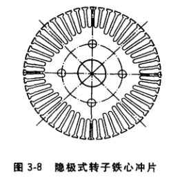
Salient pole rotor core by the uniform distribution or the entire outer circumferential groove Zhang Chong sheet size distribution trunking stacked together, shown in Figure 3-8. The iron core is directly press-fitted on the rotating shaft, and the end plates and the brackets supporting the magnetic pole windings are arranged at both ends. In order to attenuate the tooth harmonic components in the generator voltage waveform, the rotor core is generally fitted with a chute. In order to improve the parallel performance of the generator and to withstand the asymmetric three-phase load operation capability, a damping hole is also punched in the core tooth portion for embedding the damper winding.
3 pole windings. The pole winding is mounted on the salient pole rotor or embedded in the hidden pole rotor core slot. When the field current is passed through the winding, the pole core passes through the magnetic flux to establish the main magnetic field of the generator. The form of the magnetic pole winding is different from the core structure, and there are also salient pole type and hidden pole type. The salient pole type is generally made of high-strength polyester enamelled round copper wire or flat copper wire. Each pole of the split salient rotor is provided with a pre-wound magnetic pole winding. The pole winding of the integral salient rotor is wound directly on the insulated pole and should be installed between adjacent poles. block disposed between the supporting poles, so as to prevent operation of the generator windings thrown outwardly by centrifugal force from deformation and damage. The interpole spacers shall be made of non-magnetic materials such as cast aluminum alloy or cast brass alloy.
The hidden pole rotor winding is a single-layer concentric type, which is formed by winding a high-strength enamelled round copper wire, embedded in a slot-insulated rotor core slot, and the winding end and the rotor bracket are fastened by a glass fiber wire tube. Then, the non-woven glass fiber ribbon is tied along the circumference of the end, and is solidified by the rotor dipping and drying treatment.
4 bearings. The bearing supports the rotor to make the rotor run lightly. The generator is generally equipped with bearings at both ends of the rotating shaft, and the bearing outer ring is fixed in the bearing chamber or the bearing sleeve of the front and rear end covers. With uneven force due to the shaft (i.e., drive end) roller bearing used, the non-drive end extension end ball bearing. The bearing must be greased. The common grease is No. 3 lithium grease. Both ends of the bearing are sealed with a bearing cap. Bearings with a protective cover seal are used, as long as the shaft and end cap have axial thrust measures, the inner bearing cap may not be installed. The bearing inner ring and the rotating shaft adopt an interference fit, and the bearing is heated and expanded by a hot sleeve method and then sleeved to the shaft bearing block. The bearing outer ring and the end cover (or bearing sleeve) adopt the transition fit, but when machining the radial dimension of the end cover bearing chamber, it is not suitable to have a clearance fit with the outer ring of the bearing to prevent the outer ring of the bearing from slipping during the operation of the generator.
5 fans. When the generator is running, heat is generated due to various losses, and ventilation cooling must be performed. Usually, a fan is mounted on the rotating shaft, and when the generator rotates, it is discharged through the fan when it is hot. In order to reduce noise and improve efficiency, fans are often made into a backward tilt centrifugal type. Fan blades are available in cast aluminum and steel plate.
6 collector rings. The collector ring is composed of two conductive rings insulated from each other. When the generator is running, the excitation current output from the excitation power source is transmitted to the rotor winding through the brush and the collector ring. Therefore, the collector ring plays a role of transmitting the excitation current from non-rotation to rotation. In order to ensure that the collector ring works well, after it is pressed to the specified position on the shaft, the circumferential surface must be finished. When the generator is assembled, the brush working surface must also be ground so that the contact surface of the brush and the collector ring is not less than 70% of the cross section of the brush .
( 3) End caps. The end cap cooperates with the base to support the rotor. The center of the end cap has a bearing chamber hole for mounting the bearing. A generator connected to an engine, which cover the end face of the shaft extension spigot end surface with which the misalignment between the bearing housing demanding, in order to ensure the normal operation the whole assembly. The end caps are cast iron and steel welded. Some three-phase generator end cap inner holes are not directly matched with the bearing, but are matched by the bearing sleeve and the bearing, and the bearing sleeve material is cast iron.
(4) Bearing cap. A bearing cap is provided on each end of each bearing to protect the bearing and prevent grease from smashing. The bearing cap material is generally cast iron and is also processed from steel.
(5) Outlet box. The outlet box contains the terminal block and the outer casing. The terminal block is assembled or pressed from U, V, W, N posts and insulators. The three-phase AC generated by the generator stator winding must be output via the terminal block on the terminal block. The new generator generally does not have the outer casing of the outlet box, but the terminal board is installed in the excitation device box or in the small control box.
2. Working principle
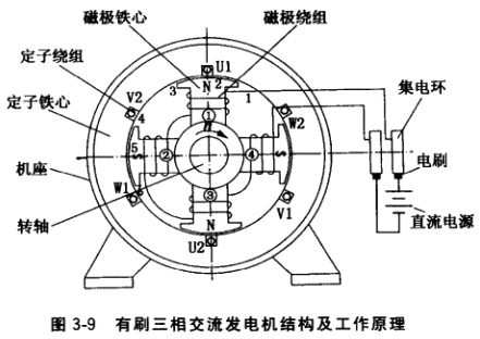
(1) The basic working principle of the generator. Figure 3-9 is a schematic diagram of the simplest 4-pole AC three-phase generator. The DC power supply supplies a DC current (ie, an excitation current) to the magnetic pole winding via a brush and a collector ring. According to the principle of generating a magnetic field around the energized coil, the four magnetic pole cores establish magnetic fields of polarity N , S , N , and S , respectively . . stator U , V, W three-phase stator windings are embedded in the core slots . The generator rotor is driven by the engine and is in the stator winding due to electromagnetic induction. The electromotive force is induced. When the stator core size and winding turns are properly designed, the generator can issue a rated voltage at the rated speed.
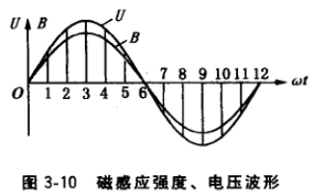
(2) Generation of alternating current. AC refers to the current or voltage that varies periodically in magnitude and direction over time in a sinusoidal fashion. The generator rotor shown in Figure 3-9 rotates clockwise. When the pair of poles N and S of the poles 1 and 2 pass over the conductor of the stator winding U1 , the voltage induced by the winding conductor is: the polarity of the pole 1 is N. When the three positions of the points 1, 2, and 3 on the surface of the pole arc pass through the winding U1 , the direction of the induced voltage of the winding is determined to be positive by the right hand rule; the polarity of the pole 2 is S, and the point 4 on the surface of the pole arc When the three positions 5, 6 pass through the winding U1 , the direction of the induced voltage of the winding is determined to be negative by the right hand rule. Since the air gap between the pole surface of the pole core and the stator core is designed to be uneven, the central air gap is small, and the air gaps on both sides are large, and the size of the air gap and the width of the pole piece are reasonably selected to make the surface along the pole arc The magnetic induction is distributed in a sinusoidal curve. When the different points of the magnetic pole pass through the winding U1, the voltage induced by the winding is also distributed in a sinusoidal curve, as shown in Fig. 3-10 , which is single-phase alternating current. The relationship between the speed of the alternator, the number of pole pairs and the frequency of the induced alternating current is: Æ’ = Pn / 60 (where Æ’ is the alternating current frequency, n is the speed, and P is the pole log ). In Figure 3-9, an N pole and an S pole form a pole pair. The generator is 4 poles, ie 2 poles.
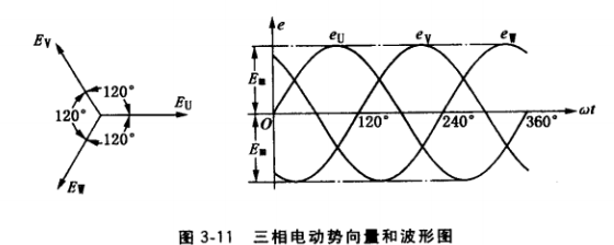
(3) Generation of three-phase alternating current. In the stator core tip of the generator shown in Fig. 3-9 , three identical windings U1U2, V1V2, and W1W2 which are mutually separated by an electrical angle of 120° are uniformly arranged along the circumference , and are called three-phase windings. When the rotor rotates, the AC electromotive force marks, eu , ev , and ew, which are separated by 120° from each other, are induced in the three-phase winding , and their vectors and waveforms are shown in Figure 3-11.
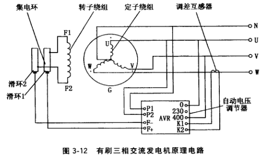
(4) Working principle of the whole machine. The schematic circuit of the brushed three-phase alternator is shown in Figure 3-12 . The direct current output from the excitation power supply (excitation power supply can be derived from the DC voltage from the DC exciter, the AC voltage from the AC exciter, the rectified DC voltage, the voltage induced by the stator secondary winding, the commutated voltage, the stator main winding tap The voltage is rectified to a DC voltage), and the excitation current is supplied to the rotor pole winding F 1 F 2 via the slip ring and the collector ring . The generator is driven by the internal combustion engine to near the rated speed, relying on the residual magnetic field of the rotor pole core (the new machine or the overhauled old machine must be magnetized, the magnetic pole core has a residual magnetic field), and the alternating current is induced in the stator winding. Since the embedded windings in the stator slots are arranged in three phases, a three-phase AC voltage is induced. Adjusting the potentiometer of the magnetic field varistor or automatic voltage regulator ( AVR ) can set the no-load voltage of the generator to the rated voltage. During the load, the rotor excitation current is automatically adjusted by an automatic voltage regulator to maintain the generator voltage constant. If the automatic voltage regulator is not equipped, the rotor excitation current is adjusted by manually adjusting the magnetic field varistor to maintain the generator voltage close to the rated value.
Larger power generators should have two or more parallel running functions. The automatic voltage regulator (AVR) required for this purpose is equipped with a tuning section, and the externally equipped differential transformer is connected to generate electricity. The output phase line of the machine, as shown in Figure 3-12, automatically adjusts the reactive load current during parallel operation of the generator.
Newly Promotion Counter With Header
1. Eye-catching header: The counter may have a prominent header that draws attention to the promotion or sale being offered.
2. Clear messaging: The messaging on the header should be clear and concise, letting customers know what the promotion is and how they can take advantage of it.
3. Attractive design: The counter may be designed in a way that is visually appealing, with attention to color, font, and layout.
4. Product display: The counter may showcase the products that are included in the promotion, making it easy for customers to see what's on offer.
5. Limited-time offer: The promotion may be time-limited, creating a sense of urgency for customers to take advantage of the deal.
6. Call to action: The counter may include a call to action, such as "Shop now" or "Learn more," encouraging customers to take the next step in the purchasing process.
7. Mobile-friendly: The counter may be optimized for mobile devices, ensuring that customers can easily access the promotion from their phones or tablets.
Newly Promotion Counter With Header,Advertising Promotion Counter Table,Pop Up Promotion Counter Portable,Display Promotion Table
SUZHOU JH DISPLAY&EXHIBITION EQUIPMENT CO.,LTD , https://www.jh-snapframe.com